
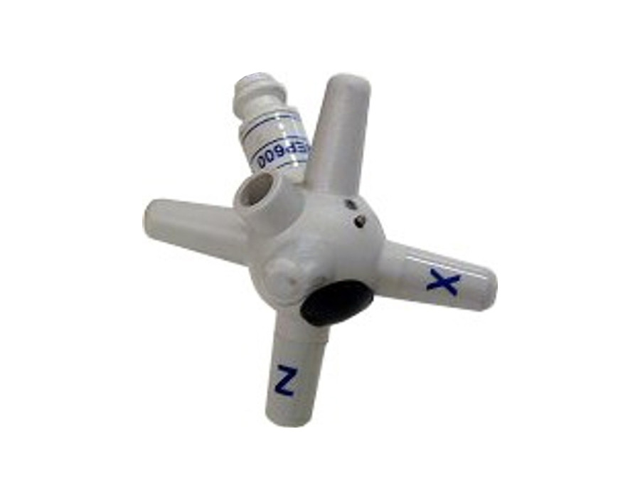
Westek Electronics supplies electric field probes for EMC test setups across Australia, with accredited calibration available on request.
Electric field probes measure RF field strength at a defined position within a radiated test environment. They help engineers establish and monitor the applied field, but a probe reading alone does not demonstrate product compliance.
How Do Electric Field Probes Support EMC Test Setups?
During radiated immunity work, amplifier output or forward-power readings do not directly show the electric field present at the equipment under test. A suitable isotropic probe measures the field in volts per metre, providing data for setting up, checking or monitoring the test environment.
This supports these tasks:
- Field levelling: Measure the field used to establish the required test level across the specified area.
- Setup checks: Compare readings after changes to the antenna, chamber layout, cabling or equipment position.
- Field monitoring: Observe whether the applied field remains within the test method’s requirements.
- Spatial assessment: Take measurements at defined positions to identify variation across a chamber or TEM/GTEM cell.
- Recorded evidence: Retain measurement data and calibration information within the laboratory’s test records.
The applicable standard, laboratory procedure and equipment configuration determine how the probe must be positioned and used.
Selecting the Correct EP-600 Series Model
We supply the EP-600 Series wideband electric field probes for EMC and EMI chambers, TEM and GTEM cells, and compatible RF measurement environments. The EP-600 to EP-604 models collectively cover frequencies from 5 kHz to 26.5 GHz, with individual field-strength ranges extending from 0.14 V/m to 1,500 V/m.
Selection must consider:
- Frequency coverage: Match the individual model to the frequencies specified by the test method.
- Field-strength range: Confirm the minimum and maximum levels suit the intended measurement.
- Probe response: Review isotropicity, flatness, linearity and uncertainty data relevant to the application.
- Physical arrangement: Consider probe size, positioning, fibre-optic communication and field disturbance.
- System compatibility: Confirm the required interface, software, meter and accessories before ordering.
A model with a higher maximum field is not automatically better if its lower measurement threshold does not suit the setup. These broadband probes also serve a different purpose from near-field RF probes used to locate emissions around PCB tracks, components or conductors. Engineers should define whether they need radiated-field measurement, near-field troubleshooting or both.
Why Calibration Status Matters
Calibration links a probe’s output to documented performance under stated conditions. Before formal testing, laboratories should check the certificate date, frequency and field-level coverage, measurement uncertainty and correction data. Accredited calibration is available for the EP-600 Series on request, but it does not compensate for poor positioning, incorrect model selection or an unsuitable test method.
The Australian Communications and Media Authority explains that evidence requirements depend on a product’s compliance level. Some products require testing, while higher-risk equipment may require testing by an accredited testing body. This regulatory process is separate from purchasing measurement equipment.
Specify Your RF Measurement Requirements
Westek Electronics supplies electric field probes and related RF testing equipment across Australia and New Zealand. We can help you compare the EP-600 Series against your required frequency range, field-strength range, interface and calibration needs.
Send us the applicable test method, target field levels, frequency range, test environment and required calibration scope. Request an equipment quote so our team can recommend a suitable probe and confirm current availability.