By Sandeep Patel
The results of not assessing loads correctly can be very costly to the contractor required to bear the cost for correcting the harmonics contribution, generally to comply with AS/NZS point of common coupling (pcc) harmonic voltage distortion limits.
Contractors involved with commercial installations have to deal with the harmonics contribution of mechanical services, lighting, and IT equipment. All too often the mechanical services switchboard is a given, and the contractor is required to incorporate harmonic mitigation for the whole installation. And – surprise, surprise – the power authority comes along and fails the installation because the mechanical services side has insufficient or no mitigation.
For industrial installations, there are often further issues: inter-harmonics caused by heavy loads switching in, burst and phasefired power control (gluing, moulding, heat treatment, etc), highly variable harmonic contributions from welders, CNCs, etc. As always, the devil is in the detail. It is critical to do a take-out, and getting it right, first off involves good estimation of harmonic loads (electronic ballasts, magnetic ballasts, “guesstimation” of likely of personal computer loads), and making sure that harmonic loads for mechanical services, etc. are taken account of and mitigated at their own switchboards. For commercial installations this might be simpler than for a large manufacturing plant. The scope of this article is limited, but software is available to help out (see Fig. 1)
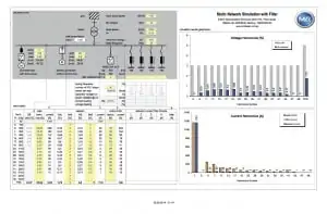
Figure 1 – In planning harmonic mitigation, predictive software is of great value. In this case, a large industrial installation is ‘mapped out’ prior to size selection of the active filters to be employed.
For many installations, a combination of active and passive filters is generally the solution. Passive filters are good for steady loads, but if required on cycling loads (eg inverter driven chillers, cool room compressors and fans etc) they need to be able to handle the variation in harmonic content (see Fig. 2). Large capacity chillers were driven by 12-pulse or even 18-pulse drives but this sort of complexity can be entirely avoided by the right choice of filter. In Figure 2, the mauve coloured line graph indicates a performance (5 per cent THID) equivalent to a 12-pulse drive.
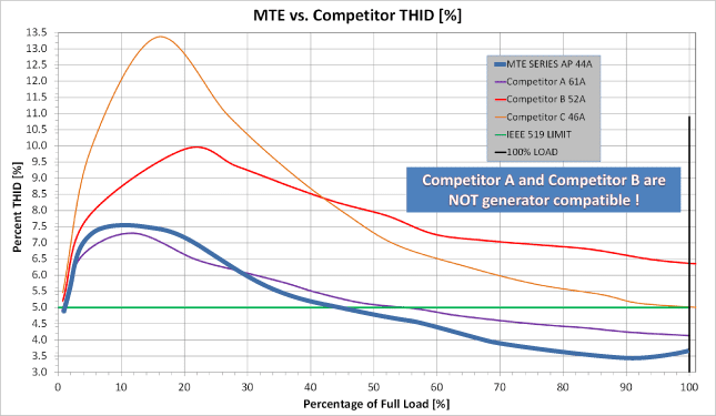
Figure 2 – The graph shows the kind of performance (mauve coloured) that a good passive filter should be capable of. The Matrix AP filter is suitable for use with standby generators – many filters have leading power factor problems.
For installations incorporating server rooms and other large IT equipment, passive filters should be chosen with an eye to their behaviour when operating with a standby generator. Leading power factor due to capacitor filtering elements should be avoided. The response of the filter in Figure 2 can be adjusted and also works well with a standby generator.
A combination of passive and active harmonic filters in large commercial buildings usually provides, if intelligently planned, a satisfactory outcome. The benefits are both now and in the future. For most installations, whether commercial or industrial, the main switchboard is the often the most sensible location for the active filtering, although from a minimum conductor energy loss aspect, filtering is best done as close to the loads as possible. However, sensible wiring schemes including separate circuit neutrals can compensate a great deal, and any increase in copper cost can be offset by the avoidance of filtering, for example at the sub-distribution boards.
Active filtering at the switchboard improves power factor, and therefore provides futureproofing in that expansion of the electrical reticulation does not have to involve upgrades. It is remarkable how many switchboards operate with doors open, and fans blowing into them in an effort to prevent excessive temperature – all caused by harmonics. The prediction of additional harmonic load current in new installati ons is generally done badly. Engineering specifications are oft en deficient and are likely to devolve the responsibility onto the electrical contractor for harmonic mitigati on ass ess ment, costing and installation. Additionally, depending on the choice of active filter, displacement power factor can also be corrected as well as phase balancing.
The use of three-level inverter active filters and adaptive-passive harmonic filters (avoidance of leading power factor) are central to effective harmonics mitigation. As is explained further on, the active filter technology provides effective harmonics mitigation under very high peak current conditions, something that is often not sufficiently taken into account.
A feature of three-level inverter technology is the ability to faithfully mimic the load current. This is particularly important when inter-harmonics, commutation and flicker noise are resent – and when is that not the case? The pretty pictures of harmonics in brochures and text books don’t occur in real life. The response time of an active filter and the voltage level of the DC link are therefore very important. Basically an active filter is an inverter fed by a DC link. In order to provide proper functioning when high peak currents are involved, the DC link must be able to
accommodate these. Instead of thinking in terms of a fundamental with sinusoidal harmonics superimposed, think of the timelapse picture of load current, and what happens when there are large inrush currents involved such as large magnetising currents drawn by switched transformer loads and motors.
Apart from the individual rms current contributions of the third, fifth and seventh and higher harmonics, the inter-harmonics caused by frequently switched loads, etc. Harmonics make for a lot of rubbish riding on top of the useful fundamental rms current. Response time in active filters is critical in dealing with the totality of everything that isn’t the fundamental current.
Hardware selection has to be governed by practicality. The active filters selected ought to be modular so that expansion is easy. Housing at least to IP 54 standards is also important because switchboards generally do not have spare room or whatever is provided over and above switchgear and metering is taken up with capacitor banks for displacement power factor correction. Modularity is key because whatever the design considerations indicated, the proof of the pudding is in the eating – and it would be too bad if it turns out a new frame size is needed to accommodate unplanned harmonic levels.
For further information, please contact us.