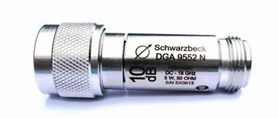
DGA 9552 N
DGA 9552 N is a bidirectional attenuator, i.e. the attenuation and power capability specification is valid for both directions.
There is a large variety of applications for this attenuator: The measuring range of a spectrum analyzer can be increased. Any kind of meter can be protected against overload; it can be used to control the linearity of a meter reading. It can minimize measurement uncertainty caused by mismatched impedances. During an EMI receiver calibration an attenuator directly at the pulse generator output is inevitable.
Every DGA 9552 N is delivered with an individual calibration of the attenuation.
Calibration data of the VSWR is available on request.
| Frequency Range: | DC … 18 GHz |
| Impedance: | 50 Ω |
| Connectors: | precision type N, acc. to MIL-STD-348 |
| Attenuation: | 3, 6, 10, 20, 30, 40 dB |
| Length: | 56.4 mm |
| Max. Power: | 5 W / 25 °C, 4 W / 45 °C, 3 W / 65 °C, |
| 2 W / 85 °C, 1 W / 105 °C | |
| 1 kW peak (5 μsec. pulse width, 0.25% duty cycle) | |
| VSWR: | less than 1.15 (DC – 4 GHz) |
| 1.20 (4 – 8 GHz) | |
| 1.25 (8 – 12.4 GHz) | |
| 1.35 (12.4 – 18 GHz) | |
| Temperature Range: | -55 … 105 °C |
| Standard: | MIL-DTL-3933 |
| Body: | Stainless steel |
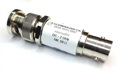
DGA 9553 BNC
DGA 9553 BNC is a bidirectional attenuator, i.e. the attenuation and power capability specification is valid for both directions.
There is a large variety of applications for this attenuator: The measuring range of a spectrum analyzer can be increased. Any kind of meter can be protected against overload; it can be used to control the linearity of a meter reading. It can minimize measurement uncertainty caused by mismatched impedances.
Optional the attenuator can be delivered with an individual calibration of the attenuation.
| Frequency Range: | DC … 2 GHz |
| Impedance: | 50 Ω |
| Connectors: | BNC |
| Attenuation: | 3, 6, 10, 20, 30 dB |
| Length: | 50 mm |
| Max. Power: | 1 W |
| VSWR: | <1.2 |
| Temperature Range: | -45 … 100 °C |
| Body: | Stainless steel |
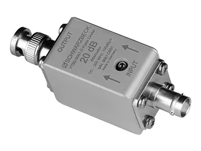
VTSD 9561 D
Diode Pulse Limiter with built-in 20 dB high power attenuator and fuse lamp to protect sensitive measuring equipment when measuring spectra with high energy. Thanks to the built-in fuse lamp serious overload situations of sensitive equipment can be recognized fast and reliably. A replacement bulb is placed inside the unit. The pulse limiter prevents expensive equipment defects. The very flat frequency response allows high measurement accuracy, even if only a few sample values are used for correction.
| Frequency Range: | DC … 200 MHz |
| Impedance: | 50 Ω |
| Insertion Loss: | 20 dB ± 0.5 dB |
| Input Connector female | BNC or N |
| Output Connectior male | BNC or N |
| Fuse Lamp | Osram 2306 |
| Replacement Lamp under Cover | 6 V 0.03 A |
| Width: | 28 mm |
| Height: | 36 mm |
| Lenght: | 88 mm |
| Weight: | 150 g |
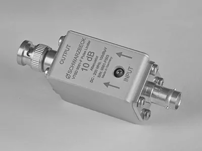
VTSD 9561 F
Diode Pulse Limiter with built-in 10 dB high power attenuator and fuse lamp to protect sensitive measuring equipment when measuring spectra with high energy. Thanks to the built-in fuse lamp serious overload situations of sensitive equipment can be recognized fast and reliably. A replacement bulb is placed inside the unit. The pulse limiter prevents expensive equipment defects. The very flat frequency response allows high measurement accuracy, even if only a few sample values are used for correction.
| Frequency Range: | DC … 200 MHz |
| Voltage Range withoute Clipping: | < 100 dBµV |
| Impedance: | 50 Ω |
| Insertion Loss: | 10 dB ± 0.5 dB |
| Frequency Response: | <± 0.5 dB |
| Input Connector female: | BNC or N |
| Output Connectior male: | BNC or N |
| Fuse Lamp: | Osram 2306 |
| Replacement Lamp under Cover | 6 V 0.03 A |
| Width: | 28 mm |
| Height: | 36 mm |
| Lenght: | 88 mm |
| Weight: | 150 g |
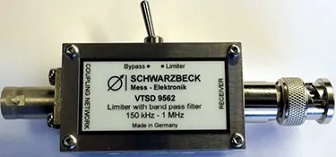
VTSD 9562
Bandpass and Limiter for Partial Discharge Measurements.
| Frequency Range: | 150 kHz … 1 MHz |
| Pass band attenuation: | 0.3 dB typ. |
| Stop band attenuation: | 90 kHz; 1.8 MHz /20 dB |
| 65 kHz; 2.8 MHz /40 dB | |
| Impedance: | 50 Ω |
| Input Connector female: | BNC |
| Output Connectior male: | BNC |
| Switching: | Bypass / Limiter switchable by toggle switch |
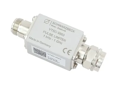
VTSD 9563
The VTDS 9563 pulse limiter is used to protect sensitive inputs of RF measuring instruments, e.g. measuring receivers or spectrum analysers. inevitable.
Every DGA 9552 N is delivered with an individual calibration of the attenuation.
Calibration data of the VSWR is available on request.
| Nominal Frequency Range: | 1 kHz … 1 GHz |
| Useable Frequency Range: | 0.1 kHz … 4 GHz |
| Insertion Loss (2 kHz < f < 2 GHz): | <1.0 dB, typ. <0.7 dB |
| VSWR (0.1 MHz < f < 1 GHz): | < 1.2 |
| Clipping: | typ. 113 dBµV / +6 dBm |
| – 1 dB Compression: | typ. 122 dBµV / +15 dBm |
| Max. cont. Power: | 10 W (+40 dBm) |
| Max. Peak Power: | 100 W (<1 µs, < 1:1000) |
| Input Connector: | N – female |
| Output Connector: | N – male |
| Length x Width x Height: | 85 x 27 x 27 mm |
| Weight: | 150 g |
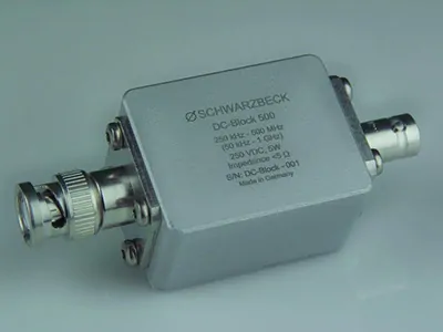
DC Block 500
DC blocking Capacitor
| Frequency Range: | 250 kHz … 500 MHz |
| (50 kHz … 1 GHz) | |
| Input Connector female | BNC |
| Output Connectior male | BNC |
| Max. Voltage | 250 V DC |
| Line – Ground | |
| Insertion Loss | <0.42 dB |
| Input – Output | |
| 250 kHz – 500 MHz | |
| Series Impedance: | <5 Ω |
| Width: | 90 mm |
| Height: | 28 mm |
| Lenght: | 35 mm |
| Weight: | 103 g |
| acc. to Standard | DIN ISO 11452-7 |